Protocols for overlaps
The Overlap of the two quantum states \(\ket{\Psi_0}\) and \(\ket{\Psi_1}\) with a kernel \(\hat{A}\) is, in general, a complex number given by
where \(\hat{A}\) is a QubitOperator i.e. it is written as a linear combination of Pauli strings \(\hat{A} = \sum_i c_i P_i\), and may be an identity.
InQuanto supports shot-based calculations of overlaps with the HadamardTestOverlap, SwapFactorizedOverlap, and ComputeUncomputeFactorizedOverlap protocols, discussed below.
HadamardTestOverlap
Let \(\ket{\Psi_0} = U_0 \ket{\bar{0}}\) and \(\ket{\Psi_1} = U_1 \ket{\bar{0}}\), where \(U_0\) and \(U_1\) are state preparation unitaries.
The HadamardTestOverlap protocol uses a “linear combination of unitaries” approach with a single ancilla on which to control the state preparation unitaries [30].
This protocol offers two measurement options: direct=False, where measurement is performed on the ancilla qubit only, and direct=True, where measurement is performed on both
the ancilla and state registers [31]. First, we discuss the direct=False case.
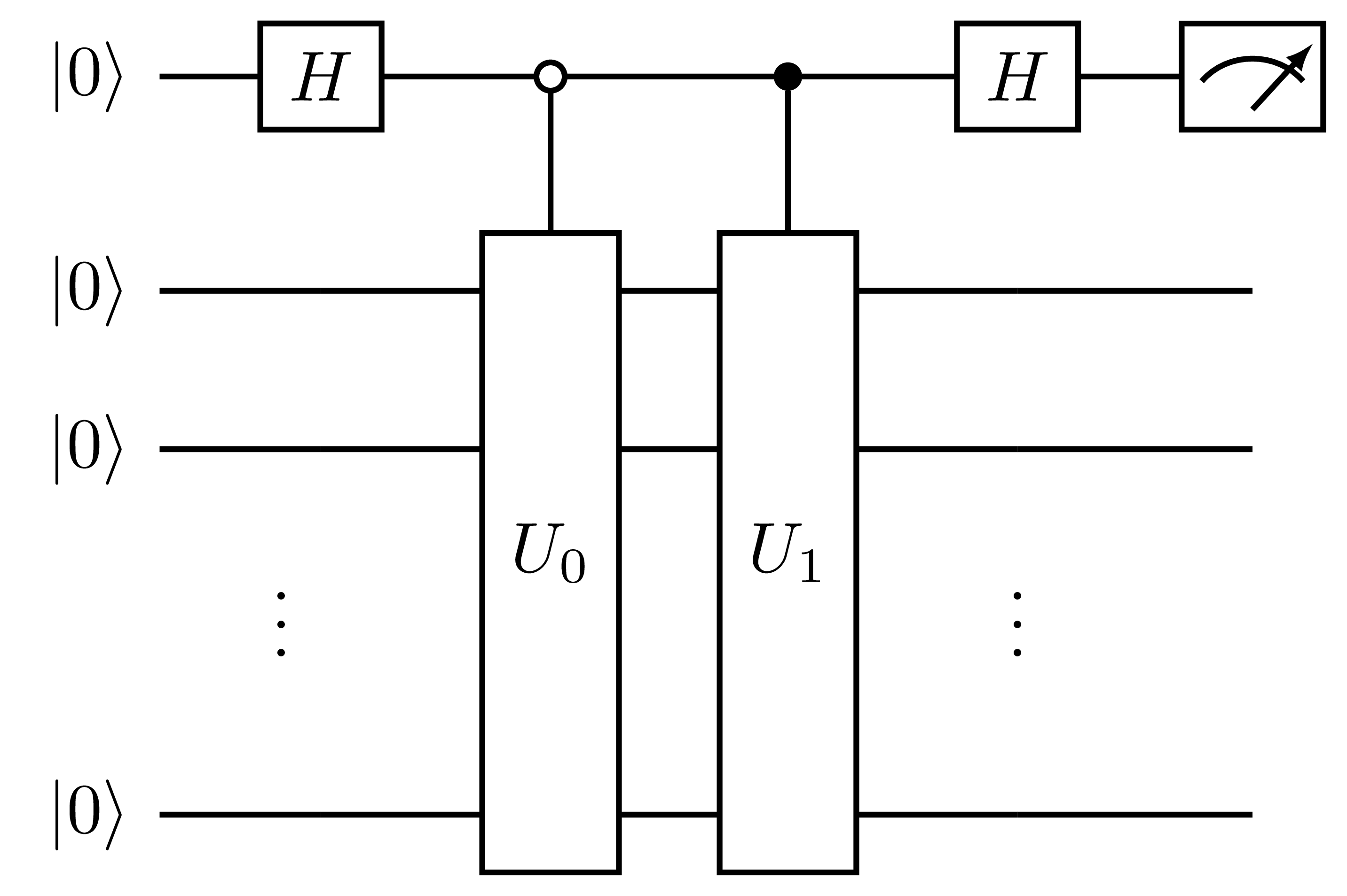
To calculate the real part of the overlap, \(\text{Re}\langle \Psi_0 | \Psi_1 \rangle\), a single circuit is required which takes the form:

Fig. 12 Measurement circuit for the real part of the overlap with identity kernel, generated by the HadamardTestOverlap protocol with direct=False. The first qubit is the ancilla and the remaining qubits comprise the state register.
This circuit prepares the quantum state:
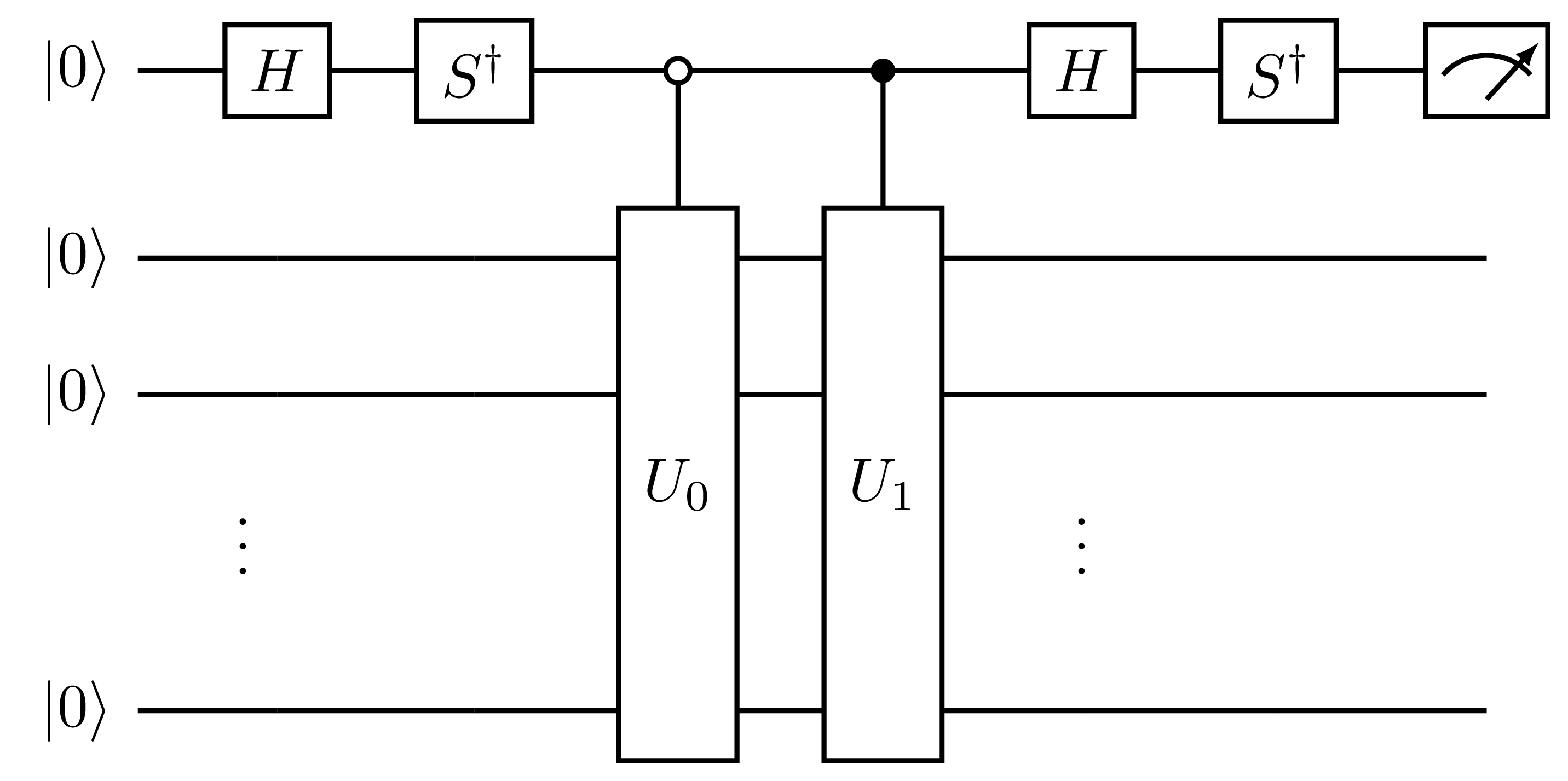
where the first ket in each term is the ancilla, and \(|\Psi_0 \pm \Psi_1\rangle = (U_0 \pm U_1)|\bar{0}\rangle\) is the state register. Given this state, the real part of the overlap is given by \(\text{Re}\langle \Psi_0 | \Psi_1 \rangle = p(0) - p(1)\), where \(p(b)\) is the probability of measuring the ancilla qubit in the state \(b\). To compute the imaginary part of the overlap, a similar circuit is required with a small modification compared to the circuit above:

Fig. 13 Measurement circuit for the imaginary part of the overlap with identity kernel, generated by the HadamardTestOverlap protocol with direct=False.
and the imaginary part is given equivalently by \(\text{Im}\langle \Psi_0 | \Psi_1 \rangle = p(0) - p(1)\).
For an overlap with a kernel \(\hat{A}=\sum_i c_i P_i\), we may write:
where each Pauli word has been appended to the \(| \Psi_1 \rangle\) state preparation; \(| \Psi_1^i \rangle = P_i U_1 |\bar{0}\rangle\). Each term in this sum is then computed
independently as described above. Thus, with direct=False, to compute the complex overlap with a kernel of \(N\) terms, \(2N\) circuits are required.
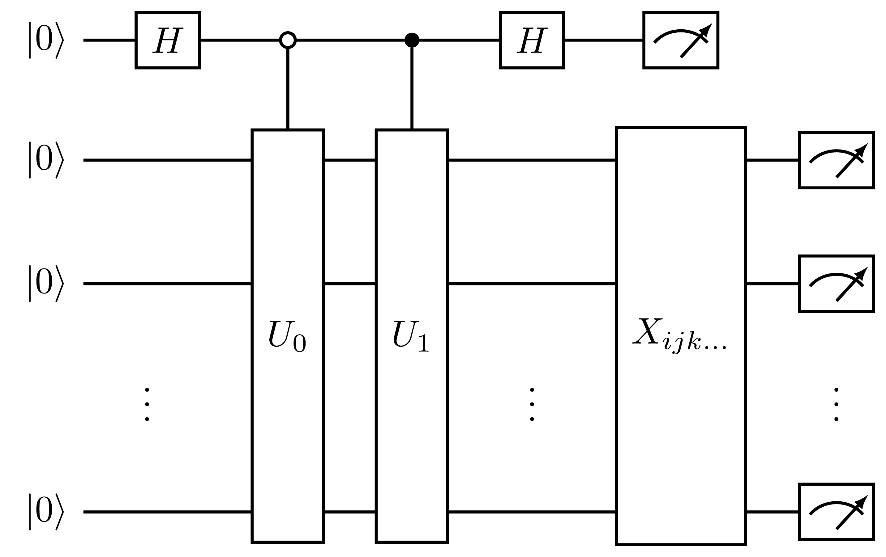
In the direct=True case, the Pauli words in \(\hat{A}\) are partitioned into simultaneously measurable sets (commuting sets, for example). Measurement circuits for each set
are then appended to the end of the state register, similarly to the Pauli averaging protocol. These circuits take the form:

Fig. 14 Measurement circuit for the real part of the overlap, generated by HadamardTestOverlap with direct=True, where \(X_{ijk\dots}\) is the set of circuits required to measure the matrix elements of a set of simultaneously measurable Pauli words. The first qubit is the ancilla and the remaining qubits comprise the state register.
In this case, measurement of the state register measures \(\langle \Psi_0 + \Psi_1 | P_i | \Psi_0 + \Psi_1 \rangle\) when the ancilla is \(|0\rangle\), and
\(\langle \Psi_0 - \Psi_1 | P_i | \Psi_0 - \Psi_1 \rangle\) when the ancilla is \(|1\rangle\). By taking a linear combination of these outcomes we can retrieve
\(\langle \Psi_0 | P_i | \Psi_1\rangle\). Thus, with direct=True, to compute the complex overlap with a kernel we require \(2N_p\) circuits, where \(N_p\) is
the number of simultaneously measurable sets of Pauli words in the kernel.
A simple example of using this protocol is given below:
from inquanto.operators import QubitOperator
from inquanto.states import QubitState, FermionState
from inquanto.ansatzes import FermionSpaceAnsatzUCCSD, HardwareEfficientAnsatz
from inquanto.computables import Overlap
from inquanto.protocols import HadamardTestOverlap
from pytket import OpType
from pytket.extensions.qiskit import AerBackend
from pytket.partition import PauliPartitionStrat

bra = HardwareEfficientAnsatz([OpType.Rx, OpType.Ry], QubitState([1, 1, 0, 0]), 2)
ket = FermionSpaceAnsatzUCCSD(4, FermionState([1, 1, 0, 0], 1))
params = (
    bra.state_symbols.construct_random()
    | ket.state_symbols.construct_random()
)
kernel = QubitOperator.from_string("(-0.1, Z0), (0.1, Z1), (0.25, X0 X1)")

ovlp = Overlap(bra, ket, kernel)

protocol = HadamardTestOverlap(
    AerBackend(),
    shots_per_circuit=int(12e3),
    direct=True,
    pauli_partition_strategy=PauliPartitionStrat.CommutingSets
)
protocol.build_from(params, ovlp)
protocol.compile_circuits()
protocol.run(seed=0)

circs = protocol.get_circuits()
print("Num circuits: ", len(circs))
print("Circuit 0 depth: ", circs[0].depth())

ovlp.evaluate(protocol.get_evaluator())
Num circuits:  4
Circuit 0 depth:  217
(-0.04965+0.024458333333333332j)
FactorizedOverlap
Protocols of the abstract type FactorizedOverlap work on pairs of ansatzes that satisfy the following conditions:
Reference preparation can be factorized out from both state preparation unitaries i.e. \(\ket{\Psi_0} = U_0 U_\text{ref}\ket{\bar{0}}\) and \(\ket{\Psi_1} = U_1 U_\text{ref}\ket{\bar{0}}\)
Both ansatzes have the same reference state preparation circuit \(U_\text{ref}\)
Non-reference factors \(U_0\) and \(U_1\) in the state preparation unitaries yield \(\ket{\bar{0}}\) when acting on \(\ket{\bar{0}}\); i.e. \(U_0\ket{\bar{0}} = U_1\ket{\bar{0}} = \ket{\bar{0}}\).
Exploitation of these properties admits more efficient overlap measurement circuits that avoid application of a control to the entire state preparations as is done in HadamardTestOverlap.
Rather, only the reference parts of the state preparations must be controlled by an ancilla qubit.
The \(U_0\ket{\bar{0}} = U_1\ket{\bar{0}} = \ket{\bar{0}}\) property is enforced by raising a TypeError upon preparation of the protocol circuits if either of the specified ansatzes is of a type that is not guaranteed to satisfy it.
All ansatz classes derived from FermionSpaceStateExp and FermionSpaceStateExpChemicallyAware are compatible with FactorizedOverlap.
These are:
Note
The chemically aware ansatzes are only supported when both bra and ket state are chemically aware. The reason for this is that the chemically aware ansatz reference circuits are in spatial orbital Jordan–Wigner encoding, and so the reference state preparation circuit is not identical to the spin-orbital Jordan–Wigner encoded reference of the non-chemically aware ansatz, even if both ansatzes share the same fermionic reference state. See here for more details.
Currently, two classes derived from FactorizedOverlap type are implemented: SwapFactorizedOverlap and ComputeUncomputeFactorizedOverlap.
These correspond to the two overlap measurement circuits presented in [32].
SwapFactorizedOverlap
This approach introduces an ancillary state register (lower in figure) to prepare the same linear combinations on the upper state register as in the case of the HadamardTestOverlap.
Since this final state is identical to that of HadamardTestOverlap, SwapFactorizedOverlap is compatible with direct operator averaging as in the circuit shown below:

Fig. 15 Measurement circuit for the real (\(\theta=0\)) or imaginary (\(\theta=\pi/2\)) part of the overlap, generated by SwapFactorizedOverlap with direct=True, where \(X_{ijk\dots}\) is the set of circuits required to measure the matrix elements of a set of simultaneously measurable Pauli words. The first qubit is the ancilla and the remaining qubits comprise the two state registers.
A simple example usage of the direct SwapFactorizedOverlap protocol is given below.
from inquanto.operators import QubitOperator
from inquanto.states import FermionState
from inquanto.ansatzes import FermionSpaceAnsatzkUpCCGSD
from inquanto.computables import Overlap
from inquanto.protocols import SwapFactorizedOverlap
from pytket.extensions.qiskit import AerBackend
from pytket.partition import PauliPartitionStrat

bra = FermionSpaceAnsatzkUpCCGSD(4, FermionState([1, 1, 0, 0], 1), 2)
ket = FermionSpaceAnsatzkUpCCGSD(4, FermionState([1, 1, 0, 0], 1), 2)
bra.symbol_substitution('{}_bra')
ket.symbol_substitution('{}_ket')
params = (
        bra.state_symbols.construct_random(seed=1)
        | ket.state_symbols.construct_random(seed=2)
)
kernel = QubitOperator.from_string("(-0.1, Z0), (0.1, Z1), (0.25, X0 X1)")

ovlp = Overlap(bra, ket, kernel)

protocol = SwapFactorizedOverlap(
    AerBackend(),
    shots_per_circuit=int(12e3),
    direct=True,
    pauli_partition_strategy=PauliPartitionStrat.CommutingSets
)
protocol.build_from(params, ovlp)
protocol.compile_circuits()
protocol.run(seed=0)

circs = protocol.get_circuits()
print("Circuit count: ", len(circs))
print("Circuit 0 depth: ", circs[0].depth())

ovlp.evaluate(protocol.get_evaluator())
Circuit count:  4
Circuit 0 depth:  142
(-0.040783333333333345+0.0032333333333333337j)
Indirect measurement is also possible with this protocol, for which the required Pauli words are appended to the ket state preparation as shown below.

Fig. 16 Measurement circuit for the real (\(\theta=0\)) or imaginary (\(\theta=\pi/2\)) part of an overlap with a non-identity kernel, generated by SwapFactorizedOverlap with direct=False, where \(P_i\) is the \(i\)th Pauli word appearing in the kernel. The first qubit is the ancilla and the remaining qubits comprise the two state registers.
A simple example usage of the indirect SwapFactorizedOverlap protocol is given below.
from inquanto.operators import QubitOperator
from inquanto.states import FermionState
from inquanto.ansatzes import FermionSpaceAnsatzkUpCCGSD
from inquanto.computables import Overlap
from inquanto.protocols import SwapFactorizedOverlap
from pytket.extensions.qiskit import AerBackend

bra = FermionSpaceAnsatzkUpCCGSD(4, FermionState([1, 1, 0, 0], 1), 2)
ket = FermionSpaceAnsatzkUpCCGSD(4, FermionState([1, 1, 0, 0], 1), 2)
bra.symbol_substitution('{}_bra')
ket.symbol_substitution('{}_ket')
params = (
        bra.state_symbols.construct_random(seed=1)
        | ket.state_symbols.construct_random(seed=2)
)
kernel = QubitOperator.from_string("(-0.1, Z0), (0.1, Z1), (0.25, X0 X1)")

ovlp = Overlap(bra, ket, kernel)

protocol = SwapFactorizedOverlap(AerBackend(), shots_per_circuit=int(12e3), direct=False)
protocol.build_from(params, ovlp)
protocol.compile_circuits()
protocol.run(seed=0)

circs = protocol.get_circuits()
print("Circuit count: ", len(circs))
print("Circuit 0 depth: ", circs[0].depth())

ovlp.evaluate(protocol.get_evaluator())
Circuit count:  6
Circuit 0 depth:  144
(-0.04296666666666668-0.000683333333333333j)
ComputeUncomputeFactorizedOverlap
An alternative protocol in the FactorizedOverlap family is ComputeUncomputeFactorizedOverlap, which takes inspiration from the ComputeUncompute method for overlaps squared,
and prepares the state:
This is accomplished by the following circuit:

Fig. 17 Measurement circuit for the real (\(\theta=0\)) or imaginary (\(\theta=\pi/2\)) part of an overlap with a non-identity kernel, generated by ComputeUncomputeFactorizedOverlap, where \(P_i\) is the \(i\)th Pauli word appearing in the kernel. The first qubit is the ancilla and the remaining qubits comprise the state register.
Which has the advantage of fewer qubits than SwapFactorizedOverlap, requiring only a single state register and one ancilla qubit, however it does produce deeper circuits.
Since projection of Pauli words on the final state does not correspond to terms in the matrix element of the kernel, it is not possible to use this protocol in conjunction with the direct operator averaging scheme described above.
A simple example usage of the direct ComputeUncomputeFactorizedOverlap protocol is given below.
from inquanto.operators import QubitOperator
from inquanto.states import FermionState
from inquanto.ansatzes import FermionSpaceAnsatzkUpCCGSD
from inquanto.computables import Overlap
from inquanto.protocols import ComputeUncomputeFactorizedOverlap
from pytket.extensions.qiskit import AerBackend

bra = FermionSpaceAnsatzkUpCCGSD(4, FermionState([1, 1, 0, 0], 1), 2)
ket = FermionSpaceAnsatzkUpCCGSD(4, FermionState([1, 1, 0, 0], 1), 2)
bra.symbol_substitution('{}_bra')
ket.symbol_substitution('{}_ket')
params = (
        bra.state_symbols.construct_random(seed=1)
        | ket.state_symbols.construct_random(seed=2)
)
kernel = QubitOperator.from_string("(-0.1, Z0), (0.1, Z1), (0.25, X0 X1)")

ovlp = Overlap(bra, ket, kernel)

protocol = ComputeUncomputeFactorizedOverlap(AerBackend(), shots_per_circuit=int(12e3))
protocol.build_from(params, ovlp)
protocol.compile_circuits()
protocol.run(seed=0)

circs = protocol.get_circuits()
print("Circuit count: ", len(circs))
print("Circuit 0 depth: ", circs[0].depth())

ovlp.evaluate(protocol.get_evaluator())
Circuit count:  6
Circuit 0 depth:  227
(-0.044441666666666664+0.004800000000000016j)