Arbitrary Angle ZZ Gates
This notebook contains a comparison of circuits with and without use of Quantinuum’s native arbitrary-angle ZZ gate in pytket. The circuit primitive, the Quantum Fourier Transform (QFT) is constructed with pytket. The inverse QFT is an important primitive used in the Phase Estimation Algorithm (PEA). PEA is used to estimate the phase corresponding to the eigenvalue of a specified unitary.
Arbitrary-angle 2-qubit gates can be used to improve fidelity of the output and to decrease 2-qubit gate depth. Specifically, the error from arbitrary-angle 2-qubit gates is less than the fixed-angle 2-qubit gate for small angles. The error from both gates is the same at angle \(\frac{\phi}{2}\). The error from arbitrary-angle 2-qubit gates increases with angle size.
Arbitrary Angle ZZ Gates
Quantinuum System Model H1’s native gate set includes arbitrary angle ZZ gates. This is beneficial for reducing the 2-qubit gate count for many quantum algorithms and gate sequences.
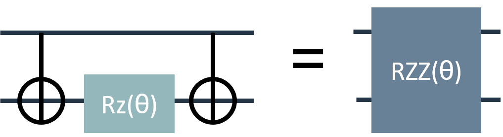
Note that $\(RZZ(\frac{\pi}{2}) = ZZ()\)$.
Quantum circuits that use the gate sequence CNOT, RZ, CNOT can be replaced with the arbitrary angle ZZ gate, shown below. This enables a lower number of 2-qubit gates in a quantum circuit, improving performance by decreasing gate errors.
This notebook demonstrates the Quantum Fourier Transform (QFT) with and without the \(RZZ\) gate.
Quantum Fourier Transform
The Quantum Fourier Transform (QFT) is an algorithm that serves as a sub-routine in multiple quantum algorithms, including Shor’s factoring algorithm. Below are two functions, written in pytket, that work together to implement the QFT.
The QFT function can be used to create the QFT. It takes the following arguments:
n: number of qubits to use in the QFT circuitarbZZ: specify whether to use the arbitrary-angle ZZ gate or not,True/False, default:Falseapprox: if set to integerk, then controlled rotations by angles less than \(\frac{\pi}{2}^{k}\) do not occur
Note: In many presentations of the QFT, the circuit includes a round of SWAP gates at the end of the circuit that reverses the order of the qubits. The QFT circuits in this tutorial do not include this final SWAP step.
Note: In pytket the \(RZZ\) gate is implemented with the \(ZZPhase\) circuit function.
import numpy as np
from pytket import Circuit
from pytket.circuit.display import render_circuit_jupyter
def control_phase(circ, theta, q0, q1, arbZZ=False):
    """circuit gadget for performing controlled-[1 0;0 e^i theta]
    Inputs:
        circ: pytket Circuit object
        theta: Z rotation angle (in units of pi)
        q0: control qubit
        q1: target qubit
        arbZZ (bool): enables arbitrary angle RZZ gate
    """
    if arbZZ == False:
        # decompose into CNOTs
        circ.Rz(theta / 2, q1)
        circ.CX(q0, q1)
        circ.Rz(-theta / 2, q1)
        circ.CX(q0, q1)
        circ.Rz(theta / 2, q0)
    elif arbZZ == True:
        circ.Rz(theta / 2, q0)
        circ.Rz(theta / 2, q1)
        circ.ZZPhase(-theta / 2, q0, q1)
def QFT(n, **kwargs):
    """
    Function to implement the Quantum Fourier Transform
    n : number of qubits
    approx: if set to integer k, then sets that largest
                 value of pi/2**k occuring in controlled rotation
    returns circ: pytket Circuit object
    """

    # optional keyword arguments
    arbZZ = kwargs.get("arbZZ", False)
    approx = kwargs.get("approx", None)

    # initialize
    circ_name = "QFT-arbZZ" if arbZZ else "QFT-fixed"
    circ = Circuit(n, n, name=circ_name)
    for j in range(n - 1):
        q = n - 1 - j
        circ.H(q)
        for i in range(j + 1):
            if approx == None or approx >= j + 1 - i:
                control_phase(
                    circ, 1 / (2 ** (j + 1 - i)), q - 1, n - 1 - i, arbZZ=arbZZ
                )
    circ.H(0)
    return circ
QFT with Fixed Angle Gates
First, create the circuit with fixed-angle gates.
n_qubits = 12
qft_fixed = QFT(n_qubits, arbZZ=False)
render_circuit_jupyter(qft_fixed)
QFT with Arbitrary Angle ZZ Gates
Second, create the circuit with arbitrary-angle ZZ gates.
qft_arbZZ = QFT(n_qubits, arbZZ=True)
render_circuit_jupyter(qft_arbZZ)
Compare Results
Now we compare the results of the QFT circuits with and without use of the arbitrary-angle ZZ gates on hardware.
State Fidelity
The QFT circuit applied to the computational basis state \(|x\rangle\) creates the state
\begin{align}
QFT|x\rangle&=\frac{1}{\sqrt{d}}\sum_{y=0}^{d-1} e^{2\pi i x y/d} |y\rangle\
&= \bigotimes_{j=0}^{n-1}\frac{1}{\sqrt{2}}\sum_{y_j=0}^1e^{2\pi i x 2^j y_j/d}|y_j\rangle\
&= \bigotimes_{j=0}^{n-1}\frac{1}{\sqrt{2}}\big(|0\rangle+e^{2\pi i x 2^j /d}|1\rangle\big)
\end{align}
where \(d=2^n\). Note that this state is unentangled. Therefore the state fidelity can be measured by applying only 1-qubit gates to map the state back to the computational basis. In the example circuits above, the initial state \(|x\rangle=|0\rangle\), and so the output state is
The state fidelity can then be measured by applying a Hadamard gate to each qubit and recording the probability of measuring \(|0\rangle\).
We define a function to measure all qubits in the Hadamard basis and append this circuit to the QFT circuits:
def meas_Had_basis(orig_circ, n_qubits):
    circ = orig_circ.copy()
    for j in range(n_qubits):
        circ.H(j)
    circ.add_barrier(range(n_qubits))
    circ.measure_all()
    return circ
qft_fid_fixed = meas_Had_basis(qft_fixed, n_qubits)
render_circuit_jupyter(qft_fid_fixed)
qft_fid_arbZZ = meas_Had_basis(qft_arbZZ, n_qubits)
render_circuit_jupyter(qft_fid_arbZZ)
Select Device
Login to the Quantinuum API using your credentials and check the device status.
from pytket.extensions.quantinuum import QuantinuumBackend
machine = "H1-1E"
backend = QuantinuumBackend(device_name=machine)
backend.login()
Circuit Compilation
Compile the circuits to the Quantinuum backend.
qft_fid_fixed_compiled = backend.get_compiled_circuit(
    qft_fid_fixed, optimisation_level=1
)
render_circuit_jupyter(qft_fid_fixed_compiled)
qft_fid_arbZZ_compiled = backend.get_compiled_circuit(
    qft_fid_arbZZ, optimisation_level=1
)
render_circuit_jupyter(qft_fid_arbZZ_compiled)
Circuit Depth and 2-Qubit Gates
Note that the circuit depth number of 2-qubit gates for the fixed-angle vs. arbitrary angle is less. The difference increases as more qubits are used.
print("Circuit Depth for fixed-angle QFT:", qft_fixed.depth())
print("Circuit Depth for arbitrary-angle QFT:", qft_arbZZ.depth())
print("Circuit Depth Difference:", qft_fixed.depth() - qft_arbZZ.depth())
print("Number of 2-qubit gates for fixed-angle QFT:", qft_fixed.n_2qb_gates())
print("Number of 2-qubit gates for arbitrary-angle QFT:", qft_arbZZ.n_2qb_gates())
print(
    "Number of 2-qubit gates Difference:",
    qft_fixed.n_2qb_gates() - qft_arbZZ.n_2qb_gates(),
)
Check Circuit Cost
Check the cost in HQC’s for each circuit. See that the Arbitrary angle ZZ QFT uses fewer HQCs, which is a plus.
Note that in this case because an emulator is used, the specific syntax checker the emulator uses is specified. This is an optional parameter not needed if you are using a quantum computer target.
n_shots = 100
print(
    "Fixed angle QFT:",
    backend.cost(qft_fid_fixed_compiled, n_shots=n_shots, syntax_checker="H1-1SC"),
)
print(
    "Arbitrary angle ZZ QFT:",
    backend.cost(qft_fid_arbZZ_compiled, n_shots=n_shots, syntax_checker="H1-1SC"),
)
Run the Circuit
Now run the circuits on Quantinuum systems. First compiling the circuits to the backend, then submitting to the device.
qft_fid_fixed_compiled_handle = backend.process_circuit(
    qft_fid_fixed_compiled, n_shots=n_shots
)
qft_fid_arbZZ_compiled_handle = backend.process_circuit(
    qft_fid_arbZZ_compiled, n_shots=n_shots
)
qft_fid_fixed_compiled_status = backend.circuit_status(qft_fid_fixed_compiled_handle)
print(qft_fid_fixed_compiled_status)
qft_fid_arbZZ_compiled_status = backend.circuit_status(qft_fid_arbZZ_compiled_handle)
print(qft_fid_arbZZ_compiled_status)
Retrieve Results
qft_fid_fixed_compiled_result = backend.get_result(qft_fid_fixed_compiled_handle)
qft_fid_arbZZ_compiled_result = backend.get_result(qft_fid_arbZZ_compiled_handle)
Analyze Results
Here the distribution of bitstrings is retrieved to inspect.
qft_fid_fixed_compiled_distro = qft_fid_fixed_compiled_result.get_distribution()
qft_fid_arbZZ_compiled_distro = qft_fid_arbZZ_compiled_result.get_distribution()
For the QFT with the appended measurement in the Hadamard basis, we expect the QFT to return all 0’s in the result bitstring. Investigating the results for both the fixed and arbitrary ZZ versions of QFT, we see this is the bitstring with the highest frequency. This is good, this is what is desired.
qft_fid_fixed_compiled_distro
qft_fid_arbZZ_compiled_distro
Comparing the results between the fixed and arbitrary ZZ versions we see that the fidelity is higher using the arbitrary ZZ gate.
print(
    "Fixed angle QFT:",
    qft_fid_fixed_compiled_distro[(0, 0, 0, 0, 0, 0, 0, 0, 0, 0, 0, 0)],
)
print(
    "Arbitrary Angle ZZ QFT:",
    qft_fid_arbZZ_compiled_distro[(0, 0, 0, 0, 0, 0, 0, 0, 0, 0, 0, 0)],
)